

Purpose of the survey
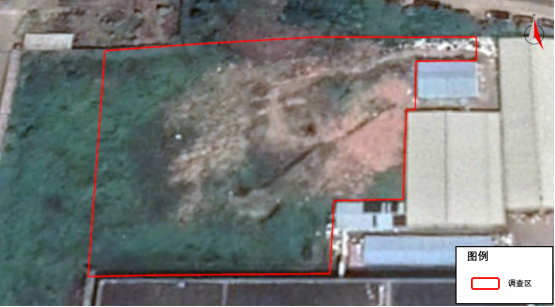
We used Electrical Resistivity Tomography and Electromagnetic Method (EM) for the project survey. The purpose of this investigation is for geophysical surveys on the field area to detect the landfill distribution range, the investigation area is about 8000m2, the scope of the survey is shown in the blue area in Figure 1-1 below.
Project status
The purpose of the investigation using the electrical resistivity method and electromagnetic method in geophysical exploration technology is:
To investigate the distribution and depth of the landfill.
Resistivity principle
The resistivity method is a geophysical method based on the difference in dielectric resistivity. The detection principle of the DC resistance method is to establish an artificial electric field by using a direct current to pass a pair of current poles A and B into the ground. By the difference in conductivity between the interlayer media, another potential pair M, N can be used to measure the potential difference between the electric field between M and N, thereby obtaining the apparent resistivity of the formation and estimating the conductivity distribution of underground formation.


EM principle
The main method of induction electromagnetic method (EM) is frequency domain electromagnetic method (FDEM), which generates an induced magnetic field in the formation through the instantaneous current of the coil, and calculates the apparent conductivity of the material by recording the phase difference of the secondary magnetic field. In a fixed case, the two-dimensional tangent plane distribution of the conductivity of the material at a specific depth can be delineated.

It is often presented in the form of a cut plane equivalent image or a single point measurement, depicting the difference in surface electrical distribution, and the conductivity of the physical unit. (mS/m), representing different heights and values in different shades.

Survey
Use the electromagnetic method to find out the contaminated area in the site, and then use resistivity method to layout the line and select the location.
To use Wenner-Schlumberger Array of resistivity method for the detection. Wenner array has better resolution for horizontal layered structures. Schlumberger array has relatively sensitive characteristics for vertical structure detection. Combining Wenner and Schlumberger array to have the good analytical data for the area. The survey distance between the electrodes is 1 meter, the resolution is about 1 meter. 6 ERT survey lines are arranged in the survey area.


Figure : conductivity result(a)result( b)trajectory
Conductivity result of EM survey display in the figure 3-1, red color represents high conductivity (low resistivity), blue-violet color represents the low conductivity range. In the conductivity distribution of the survey area, there are 4 high conductivity area (1)、(2)、(3)、(4), the conductivity is more than 100 mS/m. In other area, the conductivity is less than 50mS/m, some are less than 10mS/m.

Figure : Conductivity projection drawing
In Figure 3-2, we found that the abnormal location is in the center of the area. Because the depth of electromagnetic detection is affected by the formation material, and the depth is limited. We used resistivity method to verify the vertical actual depth and the characteristics of the buried objects
ERT result
Combining on-site hand drill data and on-site ERT detection results, speculate that the abnormal characteristics of the landfill resistivity is less than 60 Ohm-m

ERT 3D profile result
ERT result picture is shown in figure 3-3. The field line resistivity can be divided into 2 layers.
The resistivity in the longitudinal direction presents a “low-high” electrical distribution, and the first layer is a continuous relatively low resistance layer with a depth of 0-2.3 meters, the resistivity range is 15-200 Ohm-m; The depth of second layer is less than 2.3 meters, and the resistivity is around 200-1800 Ohm-m.
In ERT3 and ERT5, the anomaly of resistivity between 15-60 Ohm-m, two low-resistance anomalies are water, it is not landfill.
There is a discontinuous high-resistance layer with a resistivity higher than 500 Ohm-m in the second layer. Combined with the field speculation, the high-resistance anomaly is construction waste backfilled after the landfill was dug out or the bedrock surface.

Figure : Anomaly distribution map
1. According to the EM measurement results, the abnormality of the investigation area is located in the center of the site
2. According to the results of ERT, the abnormal area of the survey area is scattered, mainly located at 3-33 meters in ERT5 horizontal position, 0-18 meters in ERT1 horizontal position, 1-27 meters in ERT2 horizontal position, 22-27 meters in ERT3 horizontal position, and the depth is about 0-1.3 meters, drilling verification of these areas.
3. The purpose of the geophysical method is to increase the on-site information,more on-site information can better verify the accuracy and timeliness.

Industry-leading geophysical equipment and service provider supplier