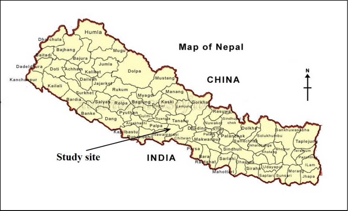
The Kerunga landslide site is located about 14.3 km NW form Kawasoti, 24 km along gravel and earthen road connecting Mahindra highway from Daldale. The landslide located at Hupsekot V.D.C, ward -5, Kerungatol of Nawalparasi district. The location of project sites are shown in Figure 1.
The main objective of the proposed study consists of mapping vertical as well as horizontal variations of electrical resistivity to enable detection of the boundaries between unconsolidated materials and rocks of the different resistivity. The objectives of the survey are as follows:
· Depth of various types of rock masses,
· Thickness of the overburdens colluvial/alluvial soil and river bed materials, if they are thick,
· Quality of the bedrocks occurring below the overburdens,
· Weak zones: Fractured zone, local fault zone, shears zones etc and propogation towards Ramche village.
· Ground water bearing formations etc.

Electrical resistivitiy of rocks
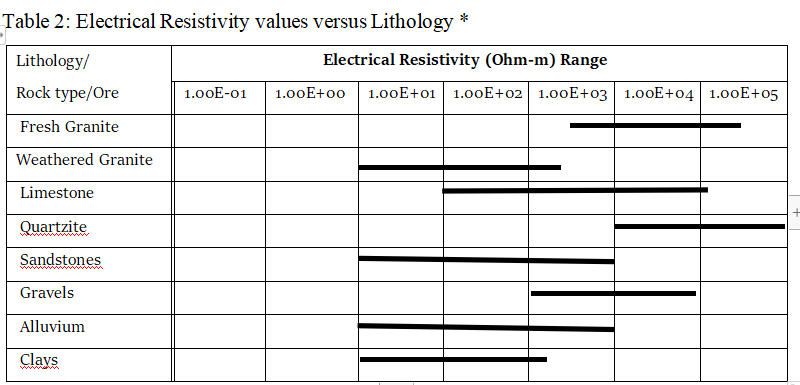
Electrical resistivity of the rocks or sediments depends on the resistivity of the rock mineral matrix and the fluid contained in its pore spaces. Rocks are composed primarily of quartz, feldspar and mica or other silicate minerals, which are poor conductors. They contain water in the pores, which is usually a better conductor. Thus the resistivity of, say, sandstone, generally depends on geometry of its pore spaces and the resistivity (or salinity) of its contained fluid. As permeability and porosity decrease, resistivity usually increases, when there is no change in formation fluid. The resistivity also depends upon the age of the rock or sediment as, with age, they become compacted and/or weathered. Compacted rocks show very high resistivity compared to unconsolidated sediments like clays, sands, gravels and so on as there will be less fluid in it. The weathered rock shows low resistivity when there is presence of water in it. Dry rocks or sediments have very high resistivity (of the order of 10,000 to 100,000 Ohm-m), whereas water bearing rocks or saturated sediments become much less resistant (10 to 1,000 Ohm-m). The resistivity of different rocks and sediments are shown in Table 2.
All rocks contain some pores in them. Under any reasonable circumstances, these poresare partly or completely filled with water. This water usually carries some salt in solution
so that the water content of rock has a far greater capacity for transmitting current than does the solid matrix of the rock unless highly conducting minerals are present.
in some rocks such as consolidated sedimentary rocks, porosity is inter-granular in nature consisting of the spaces left over after the rock grains were compacted. In other rocks and particularly in igneous rocks, porosity occurs primarily in the form of joints. in general, hard rocks are poor conductors of electricity, but geological processes like weathering, dissolution, hydrothermal alteration; faulting and shearing can alter rock to increase the porosity and permeability of rock and hence decreases resistivity. By comparison, compaction of sedimentary rock and metamorphism of all types may result in lower porosities and permeability. Resistivity is, therefore, a widely varying parameter, which changes not only from lithology to lithology, but also within a particular formation of same lithology.
Apparent resistivity values obtained in the field are not equal to the actual resistivity of the geologic units which affect the potential measured at the potential electrodes, unless measurements are being made over homogenous ground (Telford and others, 1990). At shallow exploration depth and at short current electrode spacing, shallow layers through which most of the current flows mostly influence measured apparent resistivity. As electrode spacing increases, a greater proportion of the induced current flows into deeper geologic layers, thus the response measured at the surface is reflective of the resistivity of increasingly deeper geologic units as the electrode spacing are increased. Hence as the distance between the current electrodes increases, so does the exploration depth or the depth of investigation of the survey.
Electrical resistivity tomography survey design
Electrical Resistivity Tomography survey is usually conducted following the various arrangements of four electrodes, two current (C1 and C2) and two potentials (P1 and P2) depending upon the specific purpose. There are many electrode arrangements, which can be used in the ERT field survey. These arrays have advantages and disadvantages. In some geological situations one is particularly better than the other to give better response. To map lateral changes in structures and good data acquisition with low signal-noise ratio, Dipole – Dipole electrode arrangement is better for deeper penetration where as Wenner electrode arrangement is better for smoother data quality. Other arrays seem to have a strong signal/noise ratio but smooth picture is obtained.

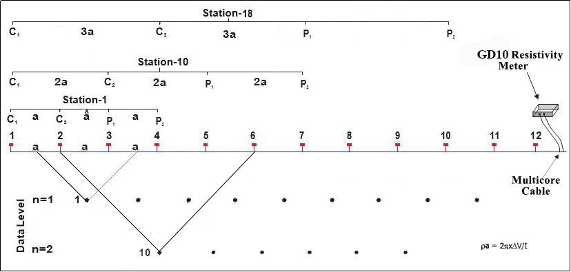
The electrical resistivity profiling was carried out using Wenner configuration. This electrode configuration offers easy deployment in the field, the separation of current and potential pairs provides low inductive noise in the data. The Wenner array records the largest horizontal anomalies in comparison to other arrays with high degree of reliable data, but its angled data measurement limits its applications. In Wenner array configuration, as shown in Figure 4, the electrodes are spread in a straight line with equal separation. The multicore cable is connected to the resistivity meter via electrode switcher. The successive measurement of resistance was carried out manually by the selection of the current (C1 & C2) and potential (P1 & P2) electrodes for each measurement by electrode switcher as instructed by resistivity meter according to 2 dimensional electrode array. The equal amount of electrode spacing is ascertained between current-current, current-potential, and potential-potential electrodes, obtained data points is dependent upon the electrode separation and length of profile. However, the increasing depth of penetration is implicit in larger values of electrode separations. The maximum depth of penetration is approximately equal to ~0.2L where ‘L’ is the total length of profile layout under normal condition. Each data value is plotted at the intersection of two line drawn 450 to the midpoint of each dipole used in the measurement.

Figure 4: Measurement of electrical resistivity using Wenner array configuration in the field
As mentioned above Wenner and Dipole - Dipole electrode configuration was employed in the present survey program. The bedrock is mainly weathered and fractured shale and sandstone. At some places they are found to be highly weathered and water saturated. These bedrocks are exposed at many places in the study area.
The field data were filtered, processed and treated with the software, RES2DINV. The software inverts the field data and calculates the appropriate model in term of resistivity and provides output in the form of resistivity contours. This inversion data is used to draw up the lithological and geological information.
Altogether six ERT profiles were surveyed at right flank of Kerunga Landslide. These ERT profiles are shown in Figure 6 to Figure 11 in the following section.

Figure 6: ERT1- Profile inversion result and interpreted lithology

Figure 7: ERT2- Profile inversion result and interpreted lithology

Figure 8: ERT3- Profile inversion result and interpreted lithology

Figure 9: ERT4- Profile inversion result and interpreted lithology

Figure 10: ERT5- Profile inversion result and interpreted lithology

Figure 11: ERT6- Profile inversion result and interpreted lithology
In total, 6 ERT profiles were surveyed at right flank of Kerunga landslide covering 1400 m. Thick to thin layer of residual soil with fragments of shale and quartzite blanketed over survey length. Moist to saturated overburden with subsurface stream channel is frequently observed in ERT profiles. The thickness of these overburden vary from few meters to 37 m. Rock is found to be very weak class and deeply weathered due to presence of water and low strength. The main conclusions are listed below:
a) Rock and soil at left flank of Landslide found to be weak and disintegrated up to residual soil.
b) Most of the surveyed area rarely consist of fresh rock up to ~ 40 m depth, covered by weathered zone.
c) Water from surface and subsurface channel found to be main cause of disintegration of rock mass. Which may be the main cause of landslide propagation.
d) ERT1 and ERT2 profiles shows that presence of subsurface water saturated zone and subsurface water channel.
e) ERT3 profile shows gradual disintegration of bedrock due to water channel.
f) ERT4 profile made up of totally weathered rock in-situ.
g) The rock at the top part of landslide found to be totally weathered as indicated by ERT5 and ERT6.
These conclusions are obtained from indirect method and should be correlated with drilling results to arrive at the overall geological conclusions.