The survey methods that will be employed in this work include:
· Resistivity method,
· Indused polarization method and
· Electromagnetic method

The resistivity method is used in the study of horizontal and vertical discontinuities in the electrical properties of the ground. It utilizes direct currents or low frequency alternating currents to investigate the electrical properties (resistivity) of the subsurface. A resistivity contrast between the target and the background geology must exist.
The electrical resistivity of a geologic unit or target is measured in ohmmeters, and is a function of porosity, permeability, water saturation and the concentration of dissolved solids in pore fluids within the subsurface. The resistance R (ohms) is either calculated from Ohm’s law (V = IR) or read off from the instrument (Terrameter). The resistivity (p) for
homogenous and isotropic medium or apparent resistivity (pa) for inhomogeneous medium
is then calculated as a function of the metered or calculated resistance(R) and the spatial electrode configuration. The resistivity (p or pa) is related to the resistance(R) via a constant known as the geometrical factor (G) which is typical of the kind of electrode configuration used.
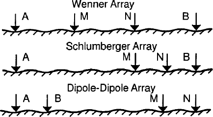
This study employs wenner array for profiling, schlumberger array for vertical electrical sounding of points in the survey area that have low apparent resistivity.

Different arrays in resistivity survey
Indused Polarization Method:
The induced polarization (IP) method is an electrical geophysical technique, which measures the slow decay of voltage in the subsurface following the cessation of an excitation current pulse. Basically, an electrical current is imparted into the subsurface, as in the electrical resistivity method. Water in the subsurface geologic material (within pores and fissures) allows for certain geologic material to show an effect called “induced polarization” when an electrical current is applied. During the application of the electrical current, electrochemical reactions within the subsurface material takes place and electrical energy is stored.
After the electrical current is turned off the stored electrical energy is discharged which results in a current flow within the subsurface material. The IP instruments then measure the current flow. Thus, in a sense, the subsurface material acts as a large electrical capacitor.
The induced polarization method measures the bulk electrical characteristics of geologic units; these characteristics are related to the mineralogy, geochemistry and grain size of the subsurface materials through which electrical current passes. Induced polarization measurements are taken together with electrical resistivity measurements using specialized IP instruments. The IP method historically has been used in mining exploration to detect disseminated sulfide deposits (lead/zinc ore), it has also been used successfully in ground water studies to map clay and silt layers which serve as confining units separating unconsolidated sediment aquifers.
Induced polarization instruments are similar to electrical resistivity instruments. There are two different types of induced polarization systems; the “time-domain”system and the “frequency-domain”system.
The TDIP method measures the voltage decay induced by the turn-off of an exciting current pulse and uses the characteristics of the decay to study the induced polarization of the soil, also known as chargeability. The equipment used in the field is the same as used for DC
measurements, and thus the set-up consists of potential and current electrodes equally distributed along a profile.
Immediately after the current is turned on, an induced potential, Vi, raises across the potential electrodes. After a charge-up effect, the primary voltage, VDC, is measured for the computation of the DC resistivity just before the current is turned off. When the current is turned off, the voltage drops to a secondary level, Vs, and then decays with time during the relaxation period. This decay curve is the target of the time domain IP method, because it is characteristic of the medium in terms of initial magnitude, slope and relaxation time. The signal Vip along the decay is usually integrated over n time windows, or gates, for the computation of the chargeability M.
Electromagnetic Method:
The electromagnetic method is a geophysical technique based on the physical principles of inducing and detecting electrical current flow within geologic strata. Electromagnetics (EM) should not be confused with the electrical resistivity method. The difference between the two techniques is in the way that the electrical currents are forced to flow in the subsurface.
In the electromagnetic method, currents are induced in the subsurface by the application of time-varying magnetic fields, whereas in the electrical resistivity method, current is injected into the ground through surface electrodes. The electromagnetic method measures the bulk conductivity (the inverse of resistivity) of subsurface material beneath the instrument’s transmitter and receiver coils. Electromagnetics can be used to locate lead/zinc vein, pipes, utility lines, cables, buried steel drums, trenches, buried waste, and concentrated contaminant plumes. The method can also be used to map shallow geologic features such as lithologic changes, clay layers, and fault zones.
A qualified geophysicist should oversee all aspects of the survey, including data collection, processing, and interpretation. Survey planning is very important in order to obtain accurate and useful information. Poor planning and survey design results in meaningless data.
The survey configuration should be selected on a site-specific basis. Traverse length and grid sizes are two parameters very crucial to an effective investigation. It is necessary to extend data collection far enough beyond the conductive target to obtain background levels, and to understand background variability.
This stage involves inputting the data obtained in the field to the computer for further processing. The computer aids the modeling for inversion of resistivity, chargeability and normalized chargeability structures in the case of resistivity and IP. In the absence of metals, IP interpretation involves definition of variability in electrochemical processes related to (1) the surface area of materials, and (2) the surface charge density or cation exchange capacity.